
Are you struggling to find out if your PCB board is working properly? Knowing how to check a PCB board with a multimeter can save you time, money, and frustration.
Whether you’re fixing a gadget or building your own electronics, this simple skill puts the power in your hands. You’ll discover easy steps to test your PCB quickly and accurately. Keep reading, and you’ll never feel lost when your circuit isn’t behaving as it should.
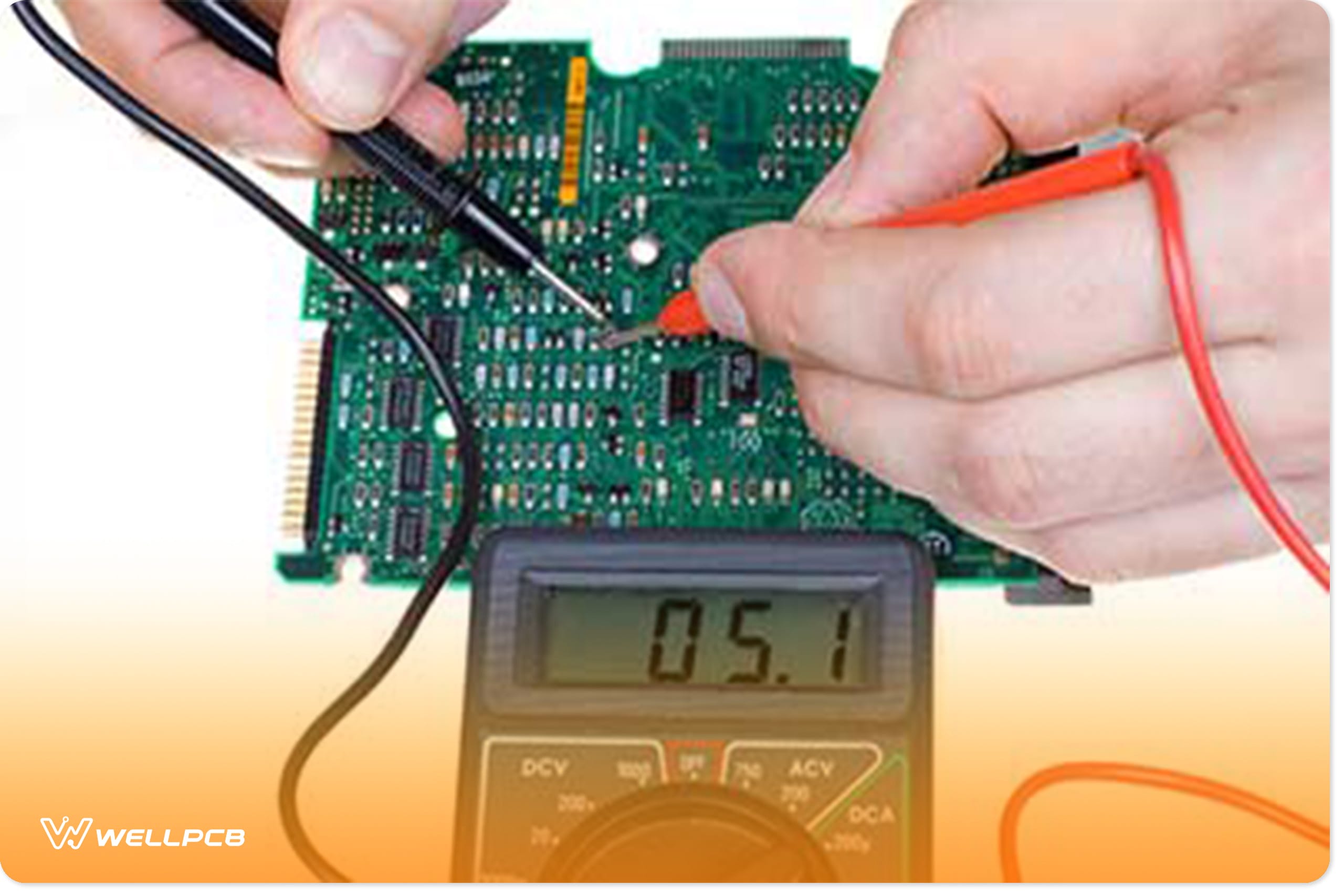
Credit: www.wellpcb.com
Tools Needed
Checking a PCB board with a multimeter requires specific tools. Having the right equipment makes the process easier and more accurate. This section covers the essential tools you need before starting.
Choosing The Right Multimeter
A digital multimeter is best for PCB testing. It offers clear readings and multiple functions. Look for a multimeter with the following features:
- Continuity test to check connections
- Resistance measurement for components
- Voltage measurement for power checks
- Diode test function
- Auto-ranging for ease of use
Choose a multimeter that is easy to handle and has a clear display. A compact design helps when working on small boards.
Additional Equipment
Besides a multimeter, some extra tools improve the testing process. These include:
- Test leads with sharp probes for precise contact
- PCB holder or stand to keep the board steady
- Soldering iron for fixing issues found
- Magnifying glass to see tiny components clearly
- Insulated gloves for safety
Having these tools ready saves time and makes your work safer and more effective.
Preparing The Pcb Board
Preparing your PCB board before checking it with a multimeter sets the foundation for accurate and safe testing. Neglecting this stage can lead to false readings or even damage to your components. Taking a few moments to get your board ready can save you hours of troubleshooting later.
Power Off And Safety Measures
Always ensure the PCB board is completely powered off before you start testing. Unplug any power sources and remove batteries if possible. This step is crucial to avoid electric shock and prevent short circuits during your multimeter checks.
Consider using an anti-static wrist strap to protect sensitive components from static electricity. Have a clean, well-lit workspace to avoid accidental slips or misreads. Remember, safety is not just about protecting yourself but also about preserving your PCB’s integrity.
Cleaning The Board
A clean PCB board makes it easier to spot faults and get reliable multimeter readings. Dust, grease, or leftover solder flux can interfere with your measurements. Use a soft brush or compressed air to remove loose debris gently.
If the board is greasy or has stubborn dirt, wipe it with isopropyl alcohol and a lint-free cloth. Avoid soaking the board; just dampen the cloth enough to clean the surface. Have you ever noticed how a simple cleaning step can reveal hidden damaged traces or burnt spots you might otherwise miss?
Setting Up The Multimeter
Setting up your multimeter correctly is the first crucial step before you start checking a PCB board. A poorly prepared multimeter can lead to inaccurate readings, which might make troubleshooting more difficult. Taking a moment to set up ensures your measurements are reliable and your work more efficient.
Selecting The Correct Mode
Start by identifying what you want to measure on the PCB—voltage, resistance, or continuity. Each function requires a different mode on your multimeter.
- Voltage (V):Use this to check power supply levels or voltage drops.
- Resistance (Ω):Ideal for testing resistors or continuity in circuit paths.
- Continuity (diode symbol or sound icon):Helps find broken traces or short circuits.
Picking the wrong mode can lead to false readings or even damage your multimeter. Have you ever assumed a setting and wasted time chasing a non-existent fault?
Calibrating The Device
Before testing your PCB, make sure the multimeter is calibrated properly. Calibration means setting the device to zero or confirming its accuracy to avoid errors.
- Check the battery level; a low battery can skew results.
- Test the leads by touching them together; the multimeter should show zero or beep for continuity.
- Use a known reference component or voltage source to verify readings.
Skipping calibration is like trying to read a map with the wrong scale. Have you ever trusted a gadget without checking if it’s working correctly first?
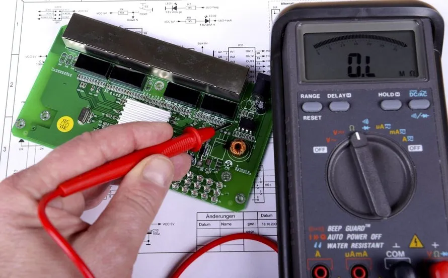
Credit: www.allpcb.com
Testing Continuity
Testing continuity is a key step in checking a PCB board with a multimeter. It helps find broken connections or short circuits. Continuity testing shows if electricity flows through a path on the board. This test is quick and gives clear results. It ensures the PCB works correctly and safely.
Identifying Test Points
Test points are spots on the PCB where you place the multimeter probes. These points include solder joints, component leads, and trace ends. Look for marked pads or holes on the board. Use the PCB schematic to find connected points. Make sure the board has no power before testing. Proper test point choice gives accurate continuity results.
Interpreting Continuity Results
Continuity results show if a path is complete or broken. A beep from the multimeter means the path is closed. No sound means no connection or a break. Some meters show a low resistance value for good continuity. High resistance or no reading means a problem. Use these results to spot faulty traces or components on the PCB.
Checking Resistance
Checking resistance is a key step in testing a PCB board with a multimeter. It helps find if components work properly or if there are faults. Resistance measures how much a component slows down electric current. Low resistance means current flows easily. High resistance means current struggles to pass.
Using the multimeter to check resistance shows if resistors match their values. It also detects open circuits where connections are broken. Short circuits with unintended paths can also be found. This ensures the PCB board functions correctly and safely.
Measuring Resistor Values
Set the multimeter to the resistance mode, often marked with the omega symbol (Ω). Touch the two probes to each end of the resistor. Read the value shown on the display. Compare this value to the resistor’s color code or labeled value.
The reading should be close to the expected resistance. Small differences may occur due to tolerance. Large differences or no reading means the resistor is faulty. Replace any resistor that shows incorrect resistance.
Detecting Open Or Short Circuits
Open circuits show infinite or very high resistance. This means no current flows through the path. Place the probes on both ends of the circuit trace or component lead. If the multimeter shows no or very high resistance, the circuit may be broken.
Short circuits have very low resistance. This means current flows where it should not. Test suspicious paths or components by measuring resistance. A near zero reading can indicate a short circuit. Check for solder bridges or damaged parts in these areas.
Measuring Voltage
Measuring voltage is a crucial step in diagnosing and repairing PCB boards. It helps you identify if the board is receiving the correct power supply and if the signals across different components are as expected. This process can seem daunting at first, but with a multimeter in hand, you can easily check the voltage levels and ensure your PCB is functioning correctly. Let’s dive into how you can effectively measure voltage on a PCB board.
Testing Power Supply
First, ensure your multimeter is set to measure voltage. Connect the black probe to the ground and the red probe to the power supply pin on the PCB. This simple connection will show you if the board is receiving the correct voltage from the power source. Imagine discovering a faulty power supply connection that was causing your whole project to stall!
It’s often the case that the power supply seems fine visually but doesn’t provide the correct voltage. A friend once spent hours troubleshooting software errors that were simply due to a low power supply voltage. Don’t let this happen to you—always check the power first!
Verifying Signal Voltages
Signal voltages are the life force that keeps your PCB functioning. Use the multimeter to measure voltage across signal points and verify they match expected levels. For example, if a component is supposed to receive 5V but only gets 3V, it might lead to unexpected behavior.
Consider a scenario where you have a series of LEDs on your board. Each LED requires a specific voltage to light up properly. If your multimeter shows varying voltage levels across them, it’s time to investigate further. This step helps you ensure consistency and reliability in your circuit’s performance.
Have you ever had a PCB that seemed to work one day and failed the next? Often, fluctuating signal voltages are the culprit. Regular voltage checks can prevent such erratic behaviors and save you time and frustration.
Inspecting Diodes And Transistors
Diodes and transistors are key parts of a PCB board. They control the flow and direction of electric current. Testing them with a multimeter helps find problems early. This saves time and avoids damage to other parts.
Using a multimeter is simple and effective. It can check if diodes and transistors work correctly or if they are damaged. Learn how to use the diode test mode and how to assess transistor functionality for accurate results.
Using Diode Test Mode
Set the multimeter to diode test mode. This mode sends a small current through the diode. It measures the voltage drop across the diode.
Connect the red probe to the anode and the black probe to the cathode. A healthy diode shows a voltage drop between 0.5 and 0.8 volts.
Reverse the probes. The multimeter should show no reading or “OL” (open loop). This means the diode blocks current in the reverse direction.
If the diode shows a reading in both directions, it is faulty. A zero or very low reading both ways means the diode is shorted. No reading in both directions means it is open or broken.
Assessing Transistor Functionality
Identify the transistor’s three pins: base, collector, and emitter. Use the multimeter in diode test mode to check each junction.
- Place the red probe on the base and the black probe on the emitter. A good transistor shows a voltage drop (usually 0.6 to 0.7 volts).
- Move the black probe to the collector. The reading should be similar to the base-emitter test.
- Reverse the probes on both junctions. The multimeter should show no reading or “OL”.
Test the collector-emitter junction by placing probes on these pins both ways. It should show no reading for most transistors.
If any reading is the same in both directions, the transistor may be damaged. This simple test helps spot faulty transistors quickly and accurately.
Troubleshooting Common Issues
Troubleshooting common issues on a PCB board with a multimeter can save you time and prevent unnecessary replacements. It’s about pinpointing exactly where the problem lies—whether it’s a damaged component or a poor connection. You’ll find that a systematic approach helps you avoid guesswork and quickly restore your circuit’s function.
Identifying Faulty Components
Start by checking individual components like resistors, capacitors, and diodes with your multimeter. Measuring resistance, capacitance, or diode forward voltage can reveal if a part is damaged or out of spec.
For example, a resistor showing infinite resistance indicates it’s broken. Similarly, a capacitor that reads open or shorted is likely faulty.
Remember to compare your readings against the component’s labeled values or datasheet. If values differ significantly, replace the suspect component before moving on.
Resolving Connection Problems
Loose or broken connections often cause intermittent or complete failure in circuits. Use your multimeter’s continuity test to quickly spot these issues.
Touch the probes to two points that should be connected. If you don’t hear a beep or see continuity on the display, the connection is broken.
Check solder joints carefully—cold or cracked solder can cause open circuits. Reflowing these joints often restores proper connectivity and saves the board from more extensive damage.
Tips For Accurate Testing
Ensuring accurate testing of your PCB board with a multimeter is essential for identifying any faults effectively. A little preparation can go a long way in avoiding errors and improving results. Here are some practical tips to help you achieve precision in your testing process.
Avoiding False Readings
False readings can lead to unnecessary troubleshooting and wasted time. To avoid them, always start with a visual inspection of your PCB board. Look for visible damages like burnt components or broken traces. This step helps you pinpoint areas that might skew your readings.
Ensure all connections are clean and secure. A loose contact can cause erratic readings, so double-checking your setup is crucial. Also, make sure your multimeter probes are in good condition; worn-out tips can contribute to inaccurate readings.
Maintaining Multimeter Performance
Your multimeter’s performance is pivotal to getting reliable results. Regular calibration is key. If you haven’t calibrated your multimeter recently, it’s time to do so. Calibration ensures that your readings are precise and trustworthy.
Additionally, keep your multimeter batteries fresh. Dying batteries can affect measurement accuracy and lead to frustration. Check the battery level before starting your testing process to ensure consistent performance.
By addressing these simple yet effective tips, you’ll enhance your PCB testing accuracy significantly. Are there other practices you follow to ensure precise readings? Share your thoughts and experiences below!
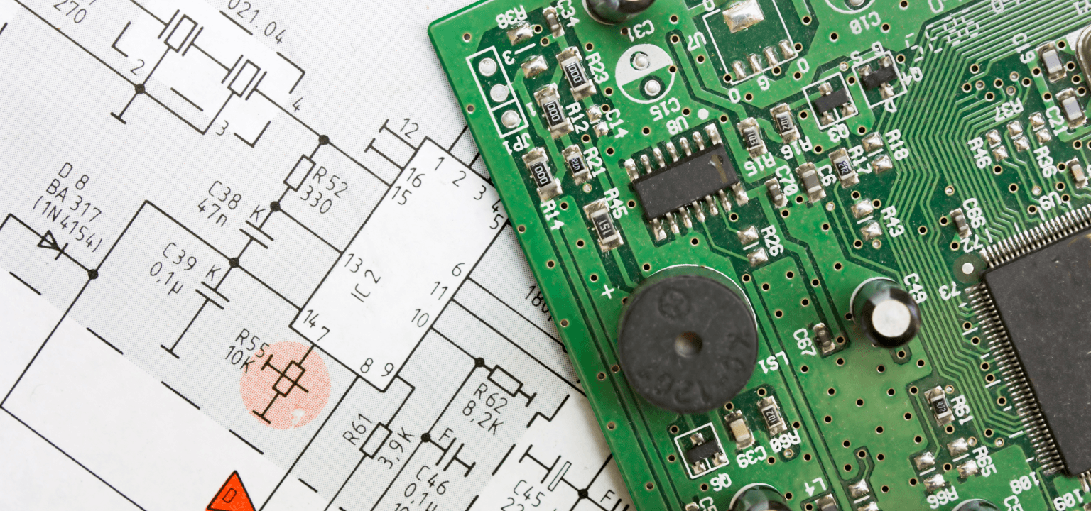
Credit: www.avanticircuits.com
Frequently Asked Questions
How Do I Test A Pcb With A Multimeter?
To test a PCB, set the multimeter to continuity or resistance mode. Check connections, components, and traces for faults or shorts.
What Multimeter Settings Are Best For Pcb Testing?
Use continuity mode to find shorts. Use resistance mode to check component values and trace continuity on the PCB.
Can A Multimeter Detect Faulty Components On Pcb?
Yes, a multimeter can identify faulty resistors, capacitors, and diodes by measuring resistance and continuity values.
How To Identify Short Circuits On Pcb Using Multimeter?
Set the multimeter to continuity mode. Probe across suspected areas; a beep indicates a short circuit.
Conclusion
Checking a PCB board with a multimeter is simple and useful. You can find broken connections and faulty parts fast. Just follow the steps carefully and take your time. A multimeter helps you save money by fixing boards yourself. Practice makes perfect, so try testing different boards.
Soon, you will feel more confident using your multimeter. Remember, safety first. Always work in a dry place and handle tools carefully. Testing PCBs improves your electronics skills and saves repair costs. Keep learning and testing to get better every day.