If you’ve ever faced a malfunctioning gadget or a tricky electronics project, you know how frustrating it can be to find out what’s wrong. Testing a circuit board with a multimeter is one of the best ways to pinpoint issues quickly and confidently.
You’ll learn simple, step-by-step methods to check your circuit board like a pro, even if you’re new to electronics. By the end, you’ll feel more in control and ready to tackle your next repair or build with ease. Keep reading—you’re just moments away from mastering a skill that can save you time, money, and stress.
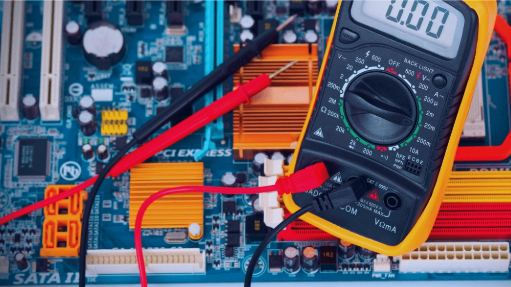
Credit: www.wellpcb.com
Preparing For Testing
Preparing for testing a circuit board with a multimeter requires careful setup. A proper start ensures accurate results and safety. You must gather the right tools, follow safety steps, and know the parts on your board.
Gathering Necessary Tools
First, collect all tools needed for the test. A good-quality multimeter is essential. Have extra probes or leads ready in case of damage. A screwdriver can help open the board’s casing. Use tweezers for small parts. Keep a clean cloth to wipe dust from the board. Organize everything on a clear workspace to avoid confusion.
Ensuring Safety Measures
Safety is critical when testing electronics. Unplug the device from power before starting. Wear safety goggles to protect your eyes. Avoid touching live wires or components. Use insulated gloves if available. Work in a dry place to reduce electric shock risk. Keep liquids and metal objects away from your workspace. Double-check your multimeter settings before testing.
Identifying Circuit Components
Understanding the board’s parts helps test effectively. Look for resistors, capacitors, diodes, and transistors. Check labels or printed codes on components. Use a circuit diagram if available. Note the location of each part on the board. This knowledge guides where to place multimeter probes. It helps you spot damaged or faulty components quickly.

Credit: www.youtube.com
Setting Up The Multimeter
Setting up the multimeter correctly is key to testing a circuit board effectively. A proper setup ensures accurate readings and protects both you and the device. Taking time to configure the multimeter before testing helps avoid errors and damage.
Choosing The Right Mode
Multimeters have different modes to measure voltage, current, and resistance. Select the mode that matches the test you want to perform. For example, use the voltage mode to check power supply levels or resistance mode to test connections.
Some multimeters have an auto mode. It detects the type of measurement automatically. This mode can be helpful for beginners but manual mode gives more control.
Calibrating The Device
Calibration keeps your multimeter accurate. Before testing, turn it on and let it warm up for a minute. Check the zero reading for resistance tests by touching the probes together.
Adjust the dial or calibration knob if the reading is off. Regular calibration is important, especially if the multimeter has been dropped or not used for long.
Selecting Proper Probes
Choose probes that fit your multimeter and suit the circuit board components. Standard probes work for most tasks. Use fine-tip probes for small, tight spaces on the board.
Inspect probes for damage or dirt. Clean or replace them to get clear readings. Good contact between probes and test points is essential for accurate results.
Testing Continuity
Testing continuity is a crucial step when you’re working with a circuit board. It helps you check if the electrical path is complete, allowing current to flow without interruption. Without this test, you might miss broken traces, faulty connections, or short circuits that can cause your project to fail.
Checking Connections
Start by setting your multimeter to the continuity mode, usually marked with a sound wave symbol. Touch the two probes together first to confirm the meter beeps, showing it’s ready to test.
Next, place one probe on one end of the connection you want to test and the other probe on the other end. A beep or a low resistance reading means the connection is good. No sound or a high reading means the path is broken or open.
It’s helpful to test all critical paths, including solder joints and wire links. A quick tip: clean any dirt or oxidation on the board first, as that can affect the reading and lead to false conclusions.
Interpreting Continuity Signals
Hearing the beep is the easiest sign that continuity exists, but the multimeter’s display gives you more details. A low resistance value, usually close to zero ohms, confirms a solid connection.
If the meter shows infinite resistance or no beep, the circuit is open somewhere. But beware: some components like resistors or diodes might naturally block continuity in one direction, so consider the component’s behavior.
Have you ever tested continuity only to find a surprising open circuit? Often, it’s a subtle crack or a cold solder joint. Patience and systematic checking can help you find these hidden issues faster than random guessing.
Measuring Voltage
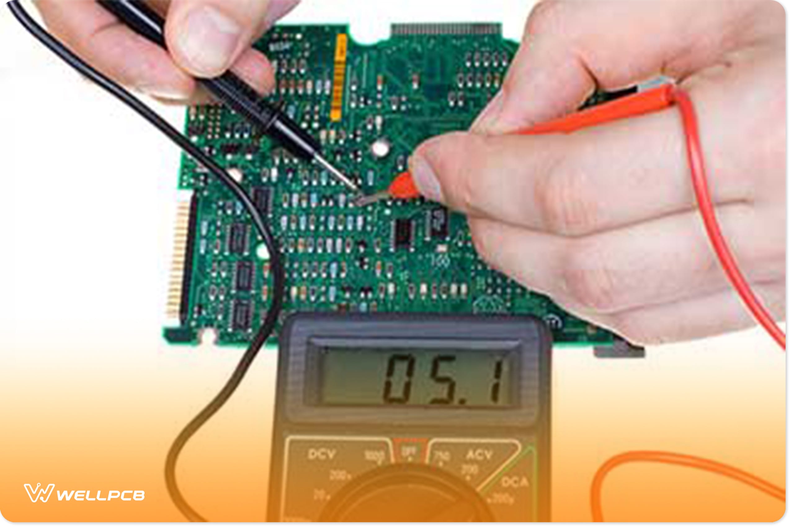
Testing a circuit board with a multimeter involves measuring voltage across components to ensure proper function. Place the multimeter probes on the circuit points to check for correct voltage levels. This helps identify faults or broken connections quickly and easily.
Measuring voltage is essential for testing circuit boards with a multimeter. It reveals the board’s power flow, ensuring components function correctly. By measuring voltage, you can diagnose issues and prevent damage. Let’s explore how to test both DC and AC voltage on a circuit board.Testing Dc Voltage
DC voltage flows in one direction. Set your multimeter to DC voltage mode. Connect the black probe to a ground or neutral point. Place the red probe on the component you need to test. The multimeter will display the voltage level. Compare this reading to the expected value. It helps identify faulty components. Ensure you test multiple points for accuracy.Testing Ac Voltage
AC voltage alternates direction. Set the multimeter to AC voltage mode. Connect the black probe to a ground or neutral point. Place the red probe on the component. Observe the reading on the multimeter screen. Compare it with the standard values. AC testing is vital for components powered by alternating current. Check multiple points to confirm stability.Reading Voltage Values
Interpreting voltage values is crucial. Ensure the multimeter is calibrated correctly. Read the numbers displayed on the screen. DC voltage readings are straightforward. AC voltage readings might vary slightly. Compare the readings with manufacturer specifications. This helps in identifying discrepancies. Proper readings ensure the circuit board functions optimally. Accurate voltage readings prevent potential issues.Checking Resistance
Testing resistance is a fundamental aspect of troubleshooting circuit boards with a multimeter. It’s crucial because detecting variations in resistance can reveal issues like short circuits or faulty components. As you navigate this process, understanding how to measure resistors and identify faulty components will empower you to resolve electrical problems effectively.
Measuring Resistors
Resistors are essential components that control the flow of current within a circuit. To measure a resistor’s resistance with a multimeter, ensure the circuit board is powered off to avoid inaccurate readings. Set your multimeter to the resistance (Ω) setting.
Place the multimeter probes on either side of the resistor. A functional resistor will show a reading close to its rated value, which is often indicated by color bands on its body. If the reading is significantly off, it might suggest a damaged resistor or connection issues.
Have you ever found yourself puzzled by unexpected readings? Double-check the multimeter settings and probe contact points. Misleading results can stem from simple oversights, so patience and precision are key.
Identifying Faulty Components
Resistance testing also helps identify faulty components within a circuit. If you encounter a resistance reading that doesn’t match the expected value, it might indicate a component is malfunctioning. This is where your detective skills come into play.
Consider a scenario where a component’s resistance value is fluctuating wildly. This can signal internal damage or wear. Use your multimeter to test other components in proximity, as one faulty part can affect the entire circuit’s performance.
Is there a way to pinpoint problems faster? Yes—develop a systematic approach to testing each component individually, recording results, and comparing them with standard values. This methodical investigation can save you time and prevent future headaches.

Credit: www.youtube.com
Testing Diodes And Transistors
Testing diodes and transistors is a crucial part of troubleshooting any circuit board. These components control the flow and amplification of electrical signals, so ensuring they work properly can save you hours of guesswork. With a multimeter, you can quickly identify if these parts are damaged or functioning as expected.
Using Diode Test Mode
Set your multimeter to the diode test mode. This mode applies a small voltage to the diode and measures the voltage drop across it.
Connect the positive lead to the diode’s anode and the negative lead to the cathode. A healthy diode usually shows a voltage drop between 0.5 and 0.8 volts.
Reverse the leads. The meter should display “OL” (open loop) or a very high reading, indicating no current flows backward. If you see a low voltage in both directions, the diode might be shorted.
Have you ever found a diode that passed the visual check but failed this simple voltage test? It’s a reminder that appearance can be deceiving in electronics.
Evaluating Transistor Functions
Testing transistors requires checking the junctions between their three pins: the base, collector, and emitter.
- Start by identifying the transistor type (NPN or PNP) and pin layout using its datasheet or online resources.
- Use the diode mode on your multimeter to test between the base and the other two pins.
For an NPN transistor, placing the positive lead on the base and negative on the collector or emitter should show a voltage drop around 0.6 to 0.7 volts. Reversing the leads should show no conduction.
Check the collector-to-emitter junction both ways; it should show no conduction in either direction if the transistor is good.
Remember, a transistor might still fail under load even if these tests look fine. But these checks help you quickly rule out many common faults.
Interpreting Test Results
After testing a circuit board with a multimeter, understanding the results is vital. The readings tell you if the components work or if there is a fault. This section helps you read those numbers and decide what to do next.
Identifying Common Issues
Check the resistance values first. A very high or infinite resistance means a broken connection or open circuit. Very low resistance might show a short circuit. Voltage readings should match the expected values in the circuit design. If voltage is too low or missing, a component may be faulty or power is not reaching the part.
Look for these signs:
- Zero or near zero resistance where it should be higher
- Infinite resistance where continuity is needed
- Voltage lower than the power supply rating
- Unexpected voltage levels on certain pins
Deciding Next Steps
After finding an issue, isolate the faulty area. Test components one by one to find the exact problem. Replace broken parts or resolder loose connections. If all tests seem normal, check the multimeter settings and retest. Document your readings for future reference.
Follow this plan:
- Confirm the faulty component with additional tests
- Repair or replace the defective part
- Test the circuit again after repair
- Seek professional help if problems persist
Tips For Effective Testing
Testing a circuit board requires care and attention to get accurate results. Simple tips can help improve your testing process and avoid common problems. Using the right approach ensures your multimeter readings are reliable and safe.
Maintaining Equipment
Keep your multimeter clean and store it in a dry place. Check the test leads for cracks or wear before each use. Replace batteries regularly to avoid weak readings. Calibrate your multimeter often to maintain accuracy. Proper care extends the life of your tool and improves performance.
Avoiding Common Mistakes
- Do not test live circuits without proper safety gear.
- Always set the multimeter to the correct mode before measuring.
- Double-check connections to avoid false readings.
- Do not touch metal parts of probes during testing.
- Disconnect power from the circuit before testing resistance or continuity.
Following these simple rules helps prevent errors and protects you from harm.
Frequently Asked Questions
How Do I Check Continuity On A Circuit Board?
Set your multimeter to continuity mode. Touch the probes to two points. A beep or zero reading confirms continuity, meaning the circuit is complete and working.
Can A Multimeter Detect Faulty Components On A Circuit Board?
Yes, a multimeter can test resistors, capacitors, and diodes. Measure resistance, voltage, and current to identify faulty components quickly and accurately.
What Multimeter Settings Are Best For Circuit Board Testing?
Use continuity mode for wiring checks, resistance mode for components, and voltage mode for power testing. Adjust settings based on the test you perform.
How To Test Voltage On A Circuit Board With A Multimeter?
Set the multimeter to DC voltage. Place the black probe on ground and red probe on the test point. Read the voltage on the display.
Conclusion
Testing a circuit board with a multimeter is simple and useful. You can find broken parts quickly by checking voltage, current, and resistance. Always follow safety steps and work carefully. Practice helps you get better and more confident. Using a multimeter saves time and money on repairs.
Keep your tools ready and test often. This skill helps keep electronics working well every day. Try it yourself and see how easy it can be.